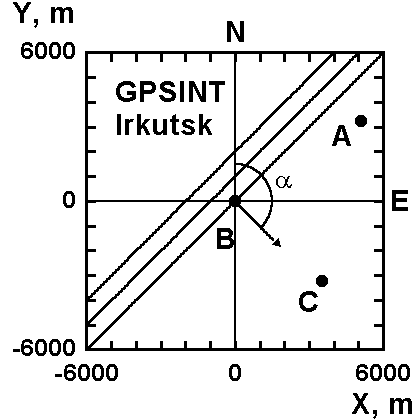
Figure 2a.
Geometry of the GPS-interferometer GPSINT. A,
B, C — reception sites spaced by about 3.5 km where dual-frequency multichannel
GPS receivers are installed. Parallel lines represent the lines of equal TEC
according simple model; the arrow shows the direction of a normal a (to these lines); and N and E are the directions to the
north (axis Y) and to the east (axis X). 